Polyphonic pickup, coil winding
repository: polypu-coil
Upon setting out on the path of developing a polyphonic pickup for guitar, we immediately arrive at the junction of having to choose a sensing technology. The options I know of include magnetic coils, piezo crystals, photoelectric diodes, and hall-effect sensors, in decreasing order with respect to how common they are.
The odd ones out are photoelectric diodes - which so far I’ve only seen in a kickstarter project that is supposedly nearing release at the time of writing - as well as hall-effect sensors - which I have briefly tried to squeeze a useful signal out of in the past - but they are just honorable mentions here, only included due to their theoretical possibility, rather than out of any practicality. Piezos rely on mechanical vibrations, and in the context of the usual construction of an electric guitar body can be quickly waved away as a possibility due to offering no promising path towards a pickup installation that provides decent isolation between strings. There may still be a point in investigating whether they are feasible, but for me, it does not invite confidence when the longer I think about this approach, the worse it seems.
After narrowing our focus to magnetic coils, we quickly find ourselves staring down an unshaven yak. After looking around for what kinds of inductors are stocked by popular electronics distributors, it seems almost impossible to choose one that will even remotely fit all our design criteria (whatever those will end up being). Personally, I realized that I wanted to avoid making any specific electronic component critical as much as possible, and could not bear to base the physical core of a project like this on a component that might go out of production on a moment’s notice. That is why, with shaving razor in hand, we now launch off towards the sub-project of building a coil winding machine.
Postmortem
It was around April 2024 that I first gave in to the temptation of building such a machine, which I later used while prototyping a polyphonic pickup. After some use, however, a few areas could have been executed on better, in retrospect. Here, I’ll introduce the machine briefly, and critique it with an eye towards the set of requirements it could imply with regards to the next iteration. To see the machine in its current form, scroll down to the section about rebuilding the circuitry.
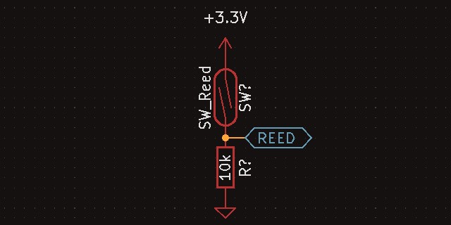
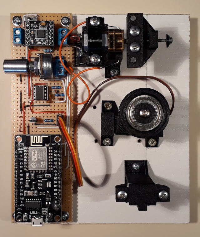
This coil winding machine used a DC motor to wind the coil, a mini servo to displace the wire horizontally, a foam pad friction tensioner to keep the wire under tension, a reed switch and magnets for turn counting, and an ESP8266 for control. The machine was running a small shell, and its operations were controlled by commands it received from a computer. The winding speed was controlled by a potentiometer. The machine counted each half-turn of the coil, and reacted by varying the displacement of the wire along the axis of the coil.
A non-exhaustive bill of materials of the key components follows below. It does not include wiring, structure, or mounting. In addition, a B micro-USB cable is necessary for connecting to the microcontroller board, as well as some kind of DC 6V source to power the motors. In my case, I used a 700mA switch wall wart power adapter that happened to be laying around.
| Description | Reference ID | Qty |
|---|---|---|
| Microcontroller module | WeMos D1 Mini | 1 |
| Geared DC motor | G12-N20 | 1 |
| Motor driver module | DRV8833 | 1 |
| Mini servo | MG90S | 1 |
| Precision timer IC | NE555P | 1 |
| Potentiometer | WH148 B50K | 1 |
| Small signal diode | 1N4148 | 2 |
| Carbon resistor | 10k | 1 |
| Carbon resistor | 1k | 2 |
| Ceramic capacitor | 10nF | 1 |
| Ceramic capacitor | 1nF | 1 |
| Reed switch | 14mm NO | 1 |
| Magnet | 3x12mm NdFeB | 2 |
| Ball bearing | 608 | 1 |
Winding regularity and manual intervention
The first problem was that it still needed constant attention and manual fine-tuning to the wire position during winding, even when it had a mechanism for displacing the wire to a specific height along the coil axis. In practice, it seemed that the wire had a tendency of bunching up in some places. When I saw this happen during a winding, I gently pushed the wire towards a valley before it could get any worse, but I’m not sure if this was necessary. You could make the argument that the height of the wire along each point of the coil axis tends to equalize due to encountering resistance while moving from a lower point to a higher one, but I have yet to test this in practice by leaving an entire winding to complete without interference.
To me, it seemed that advancing the displacement of the wire did not provide sufficient force along the coil axis to make it move evenly while it encountered resistance due to having to cross over irregularities or bumps. Approaching the problem from this angle, the force could be increased either by increasing the wire tension, or by increasing the change in angle a wire experiences after its displacement advances by a set amount. The limit around the former is determined by the wire gauge, and how easily the wire tends to snap, and becomes less effective of a solution with thinner gauges. The latter can be improved by reducing the distance the wire has to travel from its point of displacement to the coil former. Since the layout of the machine could probably allow the motors to be mounted closer together, that’s probably what I would try in the next iteration.
Servo accuracy
The second problem was that the servo did not seem to produce the displacements I would have expected it to, and I had to introduce some ad-hoc calibration for it in software, such as telling it that it was moving a 7mm lever when in reality that was only 6mm. I have yet to verify this, but it would not be surprising if these cheap hobby servos weren’t great at actually reproducing the angle that you would expect them to based on their range and the signal they are fed with. It’s possible that they are, and I didn’t account for something in how I’ve assembled my machine. So far, I’ve only heard that the behavior of these servos towards the extremes of their range isn’t the most reliable. In the next iteration, I would like to measure the rough angular accuracy of my servos, and to implement a method of calibrating the specific unit I happen to have on hand.
Reed switches and magnets
The third problem was related to turn counting, and the problems of working with a reed switch. Initially, I wanted to use reed switches and magnets due to their (technological) simplicity, in contrast to using either a hall sensor or a motor with a built-in encoder. Reed switches can be fragile, though, and they need to be handled with great care, as putting force between their leads and glass casings can fairly easily cause them to shatter. They also incur an overhead in their installed position, where they must be protected from external forces. As you may notice, the previous installation didn’t do well on either of these fronts. The leads of the reed switch were not strain-relieved in any way, and I have broken a few before figuring out how to keep them from disintegrating while futzing around with them.

One other option for magnetic sensing is some kind of hall sensor. If we accept their increased technological complexity, we could opt to use them similarly to, but instead of a reed switch, or we could seek out a version of these DC motors that come with a magnetic encoder built in. They are similarly available as the ones without, but their price difference is greater than the cost of the extra components we would need to do it ourselves.
Experimenting with the servo
After testing the machine further, let’s try to match the servo datasheet to reality.
The following measurements were done with the servo’s supply pin and ground pin connected to 6V and GND from a stabilized wall-wart, and its PWM pin was connected to a 3.3V GPIO on the WeMos D1 Mini.
Angular range
The angular range of the servo should be 180 degrees, and gently rotating it by hand while unpowered shows that the distance between its end stops is fairly close to that, it seems only a few degrees wider. I’ve heard that the end stops are generally set a bit wider than the programmable range of angles to avoid damage to the gear train during normal operation, and this agrees with that.
After verifying that the intended pulse lengths (1-2 ms) appear on the PWM pin at the intended frequency (50 Hz), I tried to determine the shortest and longest pulses the servo will respond to. The shortest pulse length was 400 us, which set it fairly close to the end stop in that direction, only about 5-10 degrees away. The longest pulse length was 2000 us, which only set it ~140 degrees higher than the position produced by the 400 us pulse. Sending a 1500 us pulse, which should correspond to the center of the range, does seem to set it roughly halfway between the two end stops, though.
The shortest pulse length doesn’t seem to correlate with what the servo is supposed to accept. What’s more, the angular range fell quite a bit short of 180 degrees. These together seem far enough out of spec to suspect that something might be wrong with the circuit still.
Reading up on these cheap servos online, and how you’re supposed to drive them, it seems that some of them work with a lower voltage level on their PWM pin than their supply pin, and some of them don’t. In my case, I was supplying them with 6.6V and controlling them with 3.3V, so I wanted to test whether mine would behave better if I brought the control voltage level up to the supply voltage.
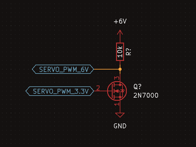
To that end, I built another breadboard prototype with a LOL1n NodeMCU V3 devboard and a level shifting circuit comprised of a 2N7000 MOSFET and a 10k resistor. The resistor was connected between the drain of the transistor and the positive supply, the 3.3V PWM from the MCU was connected to the gate pin, and the source pin was grounded. The output PWM of a higher voltage was tapped from the drain junction. In the following two experiments, the grounds of different supplies were tied together. Also, the PWM logic had to be inverted in software, to counteract the inversion of the level shifting circuit.

First, I tried to supply the servo and the level shifter from the 5V off the board. I’ll note that this is generally advised against, as these servos can draw higher currents under load than this setup can reasonably provide. Things may be fine for short motions with no external force acting against the servo, but I have to admit that right know I don’t know if the momentary peak current could damage some setups even in those conditions. Mine hasn’t exploded yet, at least. Either way, after measuring the supply to be 5V, and the PWM to be 4.8V, it doesn’t seem to matter, as the servo responds the same way as it did before.
Second, I tried to supply the servo and the level shifter from the 6.6V of the wall-wart. This should be a better setup in the sense that we could load the servo and expect the power supply to provide the current it requires. After measuring the supply to be 6.6V and the PWM to be 6.4V, and sending some various pulse lengths, the servo still seems to behave in the same way, though.
Based on the above, I think I’ll conclude that my particular unit just happens to behave like this. I have either damaged it while fumbling around with it for so long, or it was never up to spec in the first place. For now, the best I can do to account for these variations is to add some calibration options to my machine’s firmware.
Rebuilding the circuitry
After putting concerns around the servo to rest, I thought it was time to build the electrical parts of the machine again, with some changes aimed at both fixing smaller pains and at making the circuit more generic, so that it has more of a chance to be useful to others.

A non-exhaustive bill of materials is again as follows. The most important change is the addition of a MOSFET level shifter, which should bring the PWM signal of the servo up to match the level of its supply, to try to eliminate the potential problem I’ve talked about in the experiments above. Another, smaller change is the addition of a dual pole, double throw switch that swaps the PWM and GND signals on the input pins of the DRV8833 to reverse the motor’s direction.
| Description | Reference ID | Qty |
|---|---|---|
| Microcontroller module | LOL1n NodeMCU V3 | 1 |
| Geared DC motor | G12-N20 | 1 |
| Motor driver module | DRV8833 | 1 |
| Mini servo | MG90S | 1 |
| Precision timer IC | NE555P | 1 |
| N-Channel DMOS FET | 2N7000 | 1 |
| Potentiometer | WH148 B50K | 1 |
| Small signal diode | 1N4148 | 2 |
| Carbon resistor | 50k | 1 |
| Carbon resistor | 10k | 2 |
| Carbon resistor | 1k | 2 |
| Ceramic capacitor | 10nF | 1 |
| Ceramic capacitor | 1nF | 1 |
| Switch | DPDT | 1 |
| Reed switch | 14mm NO | 1 |
| Magnet | 3x12mm NdFeB | 2 |
| Ball bearing | 608 | 1 |
As it caused me some headaches - as well as the loss of a DRV8833 module - I think I should mention that, after laying out the initial schematic again and putting it together on perfboard, I sent 6V logic to its input and sleep pins, which, as it turns out, may be out of spec for the IC. Right now, I can’t find any information in the datasheet or in online forums that explicitly mentions the upper limit for these logic inputs, so I may have just damaged it during soldering or handling. Either way, it’s supposed to work at both 3.3V and 5V, so I just pulled the sleep pin to 5V with a 50k resistor, and supplied the NE555 timer from 5V as well.
Other than that, the rebuild was focused on better execution, on trying to learn from the problems of the previous board. In the hope that it may be useful to you, I would distill these tips around prototyping on perforated board as follows.
- include a sturdy, well-positioned grounding point for oscilloscope probes
- put modules and ICs on headers and sockets where possible, to ease repairs
- consider detachable internal/external connections elsewhere as well
- think twice about layout before soldering in components and connections
- drill mounting holes first to avoid stressing components
Of the above, I would like to stress the importance of safe and convenient grounding for probes. I almost had to learn this the hard way, after nearly letting the magic smoke out of either my devboard, USB port, or even worse, my oscilloscope at one point. Learning and thoroughly understanding how to use an oscilloscope safely has an immediate importance, and how to use them effectively is helpful in the long-term, so both are worth sinking some time into if you happen to gain access to one.
Lastly, some points of style include using perforated board with unconnected copper pads, with pads only on one side, pointing the conductive side of the board downwards, keeping components at the top, running shorter solder lines on the bottom, and making longer jumps with wires on the top (and not forgetting to leave adequate space for screws and mounting wherever they are necessary). These have more to do with personal style, but I thought I would include some here anyway.
Conclusion
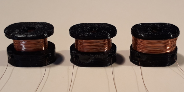
This rebuild of the circuitry will conclude this project, at least for the time being. In the end, I only managed to deal with one of the potential issues of the first iteration, which was about the accuracy of the servo. While testing the machine, I also tried to improve upon the geometry of the coil by adding a horizontal tunnel through the base of the bobbin through which I could push the trailing end of the wire after winding, and fix it in place more easily with a single drop of superglue. Before, I used to glue the trailing end onto the winding itself, which is a quite tedious and finicky way to finish a coil, so I hope this will make for a better assembly overall, in the sense of both process and result.

It feels like it is time to put this particular razor back on the shelf, and proclaim this part of the whole wretched endeavour to be a close enough shave. After all, the coils wound by this machine were always meant to make another machine hum.
created
modified