Polyphonic pickup, permalloy
repository: polypu
After a considerable detour of synchronizing the input audio data rate of I2S to the output data rate required by the USB host, now armed with the hope of not having to deal with that or other similar problems from the night terror dimension for some time, we may return to the cliffhanger of the “mixed signal” assembly.
Standing over the proverbial coffin, after seeing the noise spectra of the loudest channels, we were left wondering whether placing the digital components and their incessant electromagnetic yodeling near the sensitive magnetic transducers may have been an idea with the approximate brightness of a moonless night. While wondering, however, I have come into the possession of some thin permalloy sheets. Building them into the few prototype boards to hand seemed like an endeavor in which I only have my time to lose.
The two sheets mentioned are supposed to be made out of a nickel-iron-molybdenum alloy known as 1J85 known for its high initial permeability (a measure of magnetization produced in a magnetic field at or near 0 T) and low coercivity (a measure of the magnetic field required to reduce the magnetization back to zero). Their thicknesses (or thinnesses, if we’re being honest) are 50 um and 100 um. With all this in mind and a decent scissor in hand, let’s play a bit with this magical magnetic material.
Shielding the coils from the brains
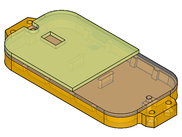
For the first experiment, I’ll place a permalloy piece between the bottom board and the middle spacer, cutting it down to a shape that has reasonable coverage while giving clearance for the mechanically interfering elements between the boards. To minimize the risk of shorting something on the board, I also sandwiched a layer of thin plastic in between, cut to the same shape.
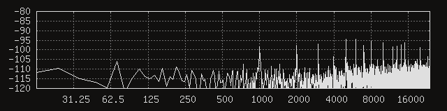
Here’s what the noise floors of the first three channels above the digital section ended up looking like during active transmission with a single layer of 50 um thick permalloy. As before the pickup was plugged in with a right-angle connector that led the USB cable down and away from it.


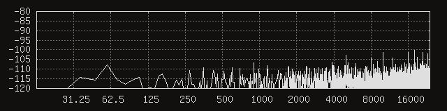
At the risk of jinxing it, I’m going to say it might be time to breathe that sigh of relief that’s been stagnating in our lungs for a couple months. While the peaks are still visible, they are greatly reduced, and the energy above 1 kHz seems much more evenly spread out in general.
Note however that it’s not just the average noise amplitude that we’re interested in improving, we also want the noise to have less prominent peaks, as the signal-to-noise ratio at the frequencies of those peaks would be greatly reduced. Although that reduction seems like it should be measurable in the average noise amplitude, I have the impression that it’s better for a given noise energy to be spread uniformly across the spectrum instead of being concentrated around a few weak points.
Also, these spectra do not perfectly match the ones that I see in the spectrum analyzer plugin I usually use in Reaper (JS: Frequency Spectrum Analyzer Meter (Cockos)) in that the peaks reach higher there. Even with the same rectangular window, I’m seeing a greater number of distinguishable peaks that are around 6-12 dB stronger.
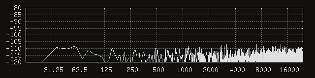
Next, let’s swap the 50 um permalloy for a 100 um piece.
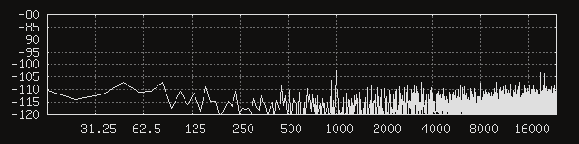


It’s hard to say if it’s better by a meaningful margin, especially when the spectrum varies enough from one measurement to the next that I find myself selecting the worse measurements to avoid making things look better than the average case. Either way, things seem fairly similar here, enough so that the 100 um thickness does not seem worth it. However, since the difference in weight and volume is insignificant here, the only thing the 50 um sheet has going for it is its workability, which (at least in my case) is outweighed by its increased cost.
Dipping into electromagnetic shielding theory
Now might be a good time to take a step back and try to wrap our heads around what just happened. Since I’m no expert on the matter, and I’m trying to build an understanding from an amalgamation of sources (from material vendors through wikipedia to academia), I’m writing this section for myself just as much as I’m writing it for you.
To start with a definition of electromagnetic shielding from wikipedia: it is the practice of reducing or redirecting the electromagnetic field (EMF) in a space with barriers made of conductive or magnetic materials. EMF shielding serves to minimize electromagnetic interference.
The shielding effectiveness (how well a shield reflects/absorbs/suppresses electromagnetic radiation) is affected by the physical properties of the material such as conductivity/permeability, as well as its physical structure and distribution.
For instance, electrically dominant waves are reflected by highly conductive metals (such as copper, silver, or brass), and magnetically dominant waves are absorbed/suppressed by materials with magnetic properties (such as martensitic, duplex, or ferritic stainless steels). Also, holes in the shield or mesh must be significantly smaller than the wavelength of the radiation that is being kept out, otherwise the shield will not effectively approximate an unbroken surface.
Electromagnetic radiation consists of coupled electric and magnetic fields. These fields interact with materials in different ways, and we can try to understand shielding through these mechanisms.
Electric fields and conductors
An electric field produces forces on the charge carriers (here, electrons) within the conductor. When applied to the surface of an ideal conductor, an electric field induces a current that causes displacement of charge inside the conductor, which cancels the applied field inside, at which point the current stops. In the process, the charges are redistributed due to electrostatic induction, and it is the opposing electric field induced by these redistributed charges that cancels an electric field external to a conductor.
The operation of the enclosure known as a Faraday cage can be described both for interior charges as well as exterior fields. For exterior fields, it is worth noting that shielding against a static electric field is mostly independent of the geometry of the conductive material, but static magnetic fields will still penetrate the shield completely.
In the case of varying electromagnetic fields, the higher the frequencies are, the better the material will resist magnetic field penetration. In this case, the shielding depends on the conductivity, the magnetic properties and the thickness of the material.
The effectiveness of a Faraday shield against time-varying fields can be described well by considerations of skin depth. With skin depth, the current mostly flows in the surface, and decays exponentially with depth through the material. A thicker shield will attenuate a given electromagnetic field better, and higher frequencies will be attenuated better by a shield with a given thickness.
Magnetic fields and conductors
A varying magnetic field within a conductor generates eddy currents that act to cancel the applied magnetic field. The variation is relative in the sense that a conductor does not respond to a static magnetic field unless it is moving relative to it. An eddy current is defined as a loop of electric current induced within a conductor by a changing magnetic field in the conductor. Eddy currents flow in closed loops within conductors, in planes perpendicular to the magnetic field.
Lenz’s law states that the direction of induced current flow will be such that its magnetic field will oppose the change of magnetic flux that caused the current flow. Eddy currents produce a secondary field that cancels a part of the external field and causes some of the external flux to avoid the conductor.
One way to describe these coupled effects is with a moving metal sheet under a magnet. Due to the relative motion, the magnetic flux through a given area of the sheet is changing, increasing as the magnet approaches and decreasing as it gets further away. This changing magnetic flux induces a circular electromotive force (emf) in the sheet, in accordance with Faraday’s law of induction, exerting a force on the electrons in the sheet, inducing a flow of current. Finally, the Biot-Savart law can relate the generated magnetic field to the flow of current, taking into account its magnitude, direction, length, and proximity.
Low-frequency magnetic fields
So far, we have skimmed over static and time-varying electric fields as well as time-varying magnetic fields. That leaves only the abyssal rabbit hole of static and low-frequency magnetic shielding unmentioned. Below the vicinity of 100 kHz, eddy current shielding starts to become ineffective. As the frequency of the magnetic field decreases towards zero, magnetostatic shielding remains as the only passive shielding solution.
Materials with high relative permeability (and a few other magnetic properties I am not qualified to describe) can provide a low reluctance path for magnetic flux. These materials can function as shields not by blocking magnetic fields but by providing a preferential path for the magnetic field lines around the shielded area. In the context of magnetic circuits, reluctance is defined as the ratio of magnetomotive force (mmf) to magnetic flux, and it represents the opposition to magnetic flux. The inverse of reluctance is permeance, which is, in general, the degree to which a material admits a flow of matter or energy.
![]()
As these lecture slides from a Torinese university describe, the shielding factor of infinite cylinders and spherical shields in the presence of uniform magnetic fields can be calculated from a material’s relative permeability, inner radius, and thickness. These idealized analyses can be helpful to first understand the factors that affect shielding, even if most shielding configurations in real-world scenarios will be far from these idealized conditions.
To finish this section with another source, this dissertation from UC about thick-film electroplated permalloy was something I also found quite interesting.
Circular coil prototype
With the crisis around the noise floor averted for the time being, my attention was seized by contemplations of crosstalk. Besides the signal-to-noise ratio, the separation between channels is probably the next most important metric of signal quality in the context of a polyphonic pickup.
As I started futzing around with designing top covers that could house permalloy snippets between the coil pairs, I couldn’t help but think that the coil geometry itself could be altered to decrease its susceptibility to crosstalk.
Staring at the wikipedia page about coils, I got the idea that minimizing the amount of coil wire running perpendicular to the neighboring string (and its magnetized area) could help with rejecting its crosstalk. This is based on the vague notion that it is the perpendicular component of a magnetic field that induces a current in a conductor. Here, it seemed like changing the cross-section of a coil from a capsule to a circle would reduce the wire mass more susceptible to crosstalk.
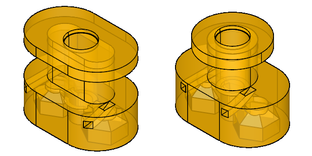
After taking a deep breath and coming to terms with the implication of having to produce another set of coils, I set to work on changing the geometry and iterating on it for the sake of printability. To start with, the wall thickness was chosen to be 0.8 mm for a minimum of strength (and reliable printing). The lower 0.6 mm of the coil mass was removed, as it was the furthest from the signal source and also the closest to the digital circuitry. The magnet was raised by 0.4 mm, to see if it could get closer to the strings without noticeably distorting their resonance. The cavities for the leading and trailing wire ends were also widened. Below are the two bobbin designs for comparison.
After a few iterations on the dimensions and the printer settings, it was time to put on an album or three and to get reacquainted with the winding machine. In this geometry, the smaller volume of the winding meant that the comfortable maximum turn count decreased from 1600 to 1000, and also that the DC resistance of a single coil dropped from 95 to 42 Ohms.
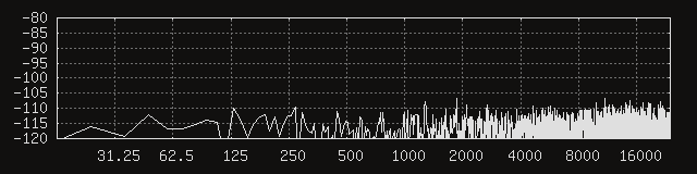
Before anything else, it would probably be a good idea to repeat the above noise floor measurements. The FFT window size remains unchanged at 4096 samples. Here are the first three channels, without any permalloy added.


Huh. It seems like things are a lot quieter, to a degree that the coil parameters would not seem to account for. In other words, the signal-to-noise at the peaks must have improved, because their amplitudes definitely dropped more than their respective signals. That’s what it looks like from eyeballing the signal levels, anyway. Moving the average coil mass a little higher doesn’t feel like a good explanation, either. My current best guess is that the circular coil geometry is somehow better at humbucking. It would not be surprising, considering the circular cross section is more regular than a somewhat funky capsule. Thus emboldened, let’s add back the 100 um permalloy shield.
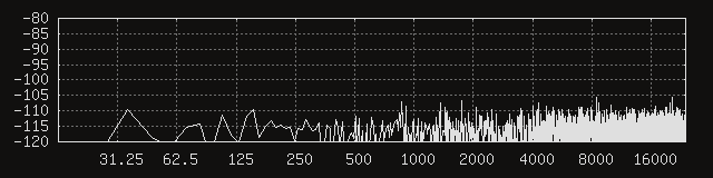
Beautiful. The distinguishable peaks seem to be gone, and the energy of the noise seems to be distributed fairly uniformly. The spectrum in Reaper seems to agree, showing a smooth, flat noise signal rolling softly on the shores of our noise floor.
created
modified