Polyphonic pickup, synchronization
repository: polypu
In hindsight, the problem I’m about to elaborate on was lurking in the background from the moment I left the tinyusb integration alone to move on to something else. Back then, after putting together the composite CDC/UAC device from various examples, it seemed to work just well enough to maintain some illusion of stability… for roughly one minute periods.
As I wanted to start slowly introducing the pickup to the idea of being near actual guitar strings, I noticed more and more that the audio stream skipped and scratched for a second or two, roughly every minute. The first failed test was sending a saw wave instead of the converted samples, and watching the spectrum in a DAW as it lost continuity. With a sense of fearful curiosity, I started toggling some GPIOs on a hunch.
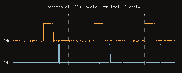
CH1 was set high at the start of
tud_audio_tx_done_pre_load_callback, which corresponded to
the isochronous transfers taking place every millisecond. CH0 went high
at the beginning of i2s_recv_callback, invoked every time a
DMA frame of a set size arrived from the ADC. The size was set to 48
samples (per channel) for the sake of this experiment so that it would
match the frequency of USB transfers at a sampling rate of 48 kHz.
The problem
If you guessed clock synchronization, please accept this virtual cookie or your preferred choice of baked delight this sentence conjures up in your mind’s eye. In other words, the clocks were drifting. They were drifting relative to each other fast enough to overlap less than every minute, causing underruns or overruns.
As this application note details, isochronous data transfers are used by USB devices designed to transfer data to or from a host at a constant rate. Furthermore, as this USB device class definition for audio devices laboriously expounds, each isochronous audio endpoint used in an AudioStreaming interface belongs to a synchronization type:
- asynchronous: producing or consuming data at a rate that is locked either to a clock external to the USB or to a free-running internal clock, these endpoints cannot be synchronized to a start of frame or to any other clock in the USB domain
- synchronous: the clock system of such an endpoint can be controlled externally through SOF synchronization, locking its sample rate to the 1 ms SOF tick
- adaptive: able to source or sink data at any rate within its operating range
To get a feel for the current situation, I started by checking the
enumerated descriptors with lsusb to see just what the
device says itself to be. To spare you the crawl across the wall of text
produced, here’s the relevant isochronous endpoint descriptor.
Endpoint Descriptor:
  bLength                 7
  bDescriptorType         5
  bEndpointAddress     0x81  EP 1 IN
  bmAttributes            5
    Transfer Type            Isochronous
    Synch Type               Asynchronous
    Usage Type               Data
  wMaxPacketSize     0x0244  1x 580 bytes
  bInterval               1
Well, it does report itself correctly as asynchronous, because it has a data rate that is locked to a free-running internal clock not synchronized to any clock in the USB domain. While this fact, considered in isolation, carries with it a sense of unadorned honesty, it also has little to do with what we want:
Synchronization
To figure out how the I2S clocks are generated, it’s time to consult the technical reference manual for the theory and esp-idf for the implementation. In this case, let’s focus on the RX clock.
The I2Sn_RX_CLK clock is the master clock of the I2Sn RX
unit, divided from four potential clock sources with a fractional
divider of the form N + (a / b). The integral part is
configured in the register I2S_RX_CLKM_CONF_REG as an 8-bit
field. The fractional values depend on the x, y, z, and yn1 fields of
I2S_RX_CLKM_DIV_CONF_REG, and the following function shows
how they are related to each other.
uint32_t i2s_get_mclk_div_conf_reg(
    uint32_t numerator,
    uint32_t denominator
){
    uint32_t x = 0, y = 0, z = 0, yn1 = 0;

    if (denominator && numerator) {
        yn1 = numerator * 2 > denominator;
        z = yn1 ? denominator - numerator : numerator;
        x = denominator / z - 1;
        y = denominator % z;
    }

    assert(yn1 < 2);
    assert(x < 512 && y < 512 && z < 512);

    return z | (y << 9) | (x << 18) | (yn1 << 27);
}
In my case, the integer and fractional parameters amounted to a
division factor of 6 + (49 / 96). Dividing the default
clock source of a 160 MHz PLL by this amount yields an MCLK (master
clock) of 24.576 MHz. To produce the BCLK (bit clock) signal
I2SnI_BCK_out, the MCLK is further divided by an integer
factor configured by the I2S_RX_BCK_DIV_NUM field of
I2S_RX_CONF1_REG. Checking that field, it held the value 4,
and dividing by that, we get the bit clock of the test configuration,
6.144 MHz. This matches the sample rate (48000) multiplied by the number
of TDM slots (8) and the bit depth (16).
If we dig down in the tree, we can find the platform-specific header
components/soc/esp32s3/register/soc/i2s_struct.h that
contains the definitions of these registers in code, which I’ll include
here as excerpts.
union {
    struct {
        uint32_t rx_clkm_div_num : 8;
        uint32_t reserved8       : 18;
        uint32_t rx_clk_active   : 1;
        uint32_t rx_clk_sel      : 2;
        uint32_t mclk_sel        : 1;
        uint32_t reserved30      : 2;
    };
    uint32_t val;
} rx_clkm_conf;
union {
struct {
uint32_t rx_clkm_div_z : 9;
uint32_t rx_clkm_div_y : 9;
uint32_t rx_clkm_div_x : 9;
uint32_t rx_clkm_div_yn1 : 1;
uint32_t reserved28 : 4;
};
uint32_t val;
} rx_clkm_div_conf;Knowing the above, it seems like it may be possible to tweak the
register holding the fractional values back and forth ever so gently to
keep acquisition to the pace dictated by the USB host. Immediately, the
worry of causing glitches or jitter in the generated clocks rears its
head, but it’s hard to say whether that would be a problem before
actually trying. For now, I’ll just stick to writing the entire register
at once through the val member.
After some initial confusion, I managed to figure out a relationship
between the interference pattern of the kilohertz signals on the scope
and the fractions held by the rx_clkm_div_conf register.
This was possible by eyeballing the beat frequency between the two
signals, and estimating the ratio of their frequencies from that.
Specifically, shifting the z field up or down by a single value
produced a drift between the signals that made them overlap at their
rising edges roughly every 20-25 seconds. This means that the beat
frequency between these signals was 0.05 Hz at most. Since the beat
frequency is the absolute difference between the frequencies of two
simultaneous tones, this results in a frequency ratio of
1000.05 / 1000 = 1.00005. This is roughly a tenth of a cent, which is
1.000577 and change.
The control loop that automated this tuning ended up being a signed
counter that increments or decrements based on whether the halfway point
between two sample blocks being completed is ahead or behind the point
in time when the pre load callback runs. When the counter exceeds a
threshold (say, 250 out of 1000 transfers per second) either way, a new
32-bit value is loaded for the rx_clkm_div_conf register,
and the counter is reset.
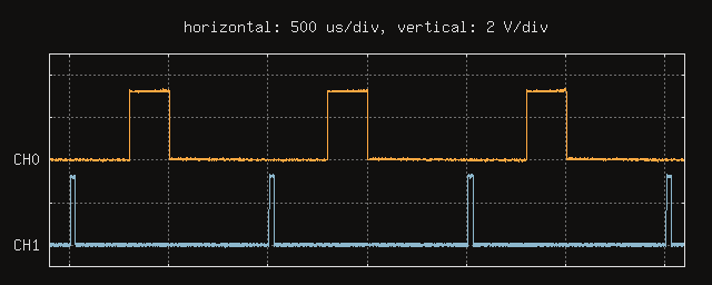
Here’s the trace showing this in action, now aligned on the falling edge of CH0, as it represents the time a block is fully processed and ready to be passed to tinyusb. The pre load callback ends up staying fairly close to a 500 us offset from block completion.
One consequence of this synchronization method is that supporting different sample rates and bit depths automatically becomes somewhat difficult, if we expect high precision. Not that I would have support for other data rates at this point, but now there’s one more step to be made before supporting a new rate: finding an appropriate set of values for the divider register. Maybe there’s a way that could be made automatic as well, but there are problems with finding fractions that yield small enough differences in frequency to avoid audible artifacts.
For the time being, I have settled for supporting only a set of data rates where I can verify synchronization, at least with my hardware. Also, instead of deriving them from fractions, I chose the values for the divider register by just modifying the z field.
created
modified